
Subsea pipeline freespan analysis

Scope
We were contracted to support our client to undertake a span assessment for its end-customer in Thailand. Scope included:
Producing updated span screening tables for ten water injection and process pipelines ranging in size from 6” to 24”
Identify all spans on the recently surveyed 8”, 16” and 24” pipelines which exceed screening limits based on the operating life of the field
Identify how many interacting span groups were present on the same 8”, 16” and 24” pipelines
Abaqus was used to complete the Finite Element Analysis (FEA), Mathcad was deployed to complete the assessment, and FEA post-processing was conducted with Excel (for handling significant numerical data).
What is a pipeline freespan
A subsea pipeline span is a section of pipe that is suspended above the seabed rather than being in direct contact with, or buried within, it. This situation can arise from natural causes like seabed erosion or can be an outcome of the pipeline installation process. Unsupported sections can be a structural vulnerability and present operational risk. Such spans can be screened against acceptance criteria to help operators determine their severity. Spans found to be outside acceptance criteria can be put through more rigorous and detailed analysis to determine if remedial work is required.
What is a span screening table?
Screening tables present the calculated fatigue lives for a range of span lengths, similar to the one shown below. These help pipeline surveyors identify spans with fatigue lives shorter than the pipelines expected operating life. For example, if the table below was for a field with a service life of 35 years, then spans of 70 m or longer would need to be analysed to accurately determine their risk of failure and recommendations made on possible remediation works.
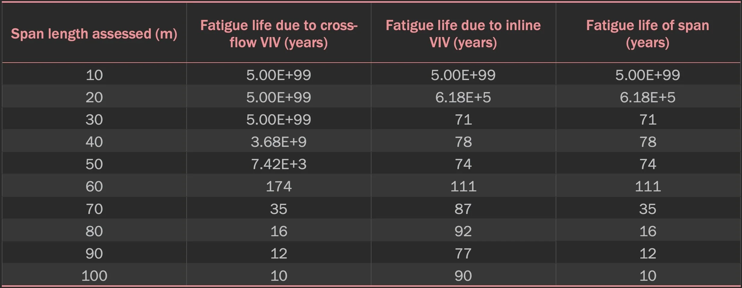
Example span screening table
Our approach
Data review and initiation
We reviewed all customer provided documentation and data like pipeline surveys, drawings, field layouts, spool-piece drawings, and alignment sheets to comprehend the pipeline systems.
Key input data was extracted from provided information and stored in a custom data register for review, approval, and efficient access.
We setup a document register to support the quick identification of appropriate data sources for each engineering task.
A calculation register was built to log all calculations, load cases, and revisions. This was critically important given that number of cases that needed to be undertaken for the range of pipelines, spans lengths, pipeline coatings etc.
Prepared quality control forms for calculation and FEA model sign-off.
Span assessment
Span acceptability was determined based on its calculated fatigue life, assuming span formation at commencement of operation.
It was agreed that the screening tables would present fatigue lives for spans on each pipeline ranging in length from 10 m to 100 m, in 10 m increments; providing lookup tables to efficiently assess spans from survey data.
Fatigue damage was determined for each spans in accordance with DNVGL-RP-C203, using the most onerous S-N curves specified for hot spots at the weld root or cap.
Where pipelines of the same diameter had sections of concrete coating, separate analyses were completed for the non-coated and coated sections; these results of these analyses was presented in their own screening tables.
The assessments consider fatigue due to excitation of both cross-flow and in-line VIV modes under direct current loading.
Fatigue damage due to wave action (fatigue waves rather than extreme waves) was determined to be negligible due to the low wave-induced velocities predicted at the pipeline depth(s).
Other sources of fatigue within the pipeline, such as operational pressure and temperature cycling and installation fatigue, were assessed explicitly. These had been accounted for in the significant conservatism of the S-N curves and the associated safety factors applied to fatigue assessments.
Interacting spans were identified using guidance in DNVGL-RP-F105 and assessed separately.
The analysis included over 100 different cases. We incorporated efficiencies into the project where possible to reduce chargeable hours. One of these involved embedding an Excel workbook into Mathcad to act as an input lookup table based on the case being run. This saved significant time preparing the inputs for each of the over 100 cases.
Survey data for the 8”, 16”, and 24” pipelines were reviewed to identify spans which exceeded each pipeline’s single span limit.
Conclusions
Screen tables
Twelve screening tables (similar the one previously shown) were created for each pipeline diameter and coating combination. These were shared with client in a technical note.
8”, 16” and 24” span limits and interactions
The screening limit for the 8” pipeline was calculated to be 90 m. This was determined as the longest span that could have been present since installation without a predicted fatigue life shorter than the pipeline’s operating life.
The 16” and 24” pipelines shared the same limit of 70 m. Again, these were determined as the longest spans that could have been present since installation without predicted fatigue lives shorter than the pipelines’ operating lives.
It was identified that two spans on the 8” pipeline, three on the 16”, and five on the 24” exceed their respective screening limited. The locations of these spans and their measured lengths were included in the post-analysis report.
Span interaction was identified on all three pipelines. The total number of interacting span groups for the 8”, 16”, and 24” pipelines was one, seven, and seventy-one respective. It was recommended that these groups be assessed using FEA to determine their risk.
Summary
In partnership with our client, we successfully conducted a comprehensive subsea pipeline span assessment. Utilising FEA software and Mathcad, we created span screening tables for ten different pipelines and identified spans exceeding operational limits in 8", 16", and 24" pipelines. We also identified interacting spans that require further scrutiny. Through our meticulous data management and streamlined computational approaches, we were able to complete over 100 different analysis cases efficiently. Our work has helped the end-customer mitigate operational risks associated with pipeline spans.
Let diver™ solve your toughest project challenges
At diver™, we partner with you to tackle your most challenging projects, bringing a data-driven, solution-focused approach that empowers your team and drives project success. Start your journey toward a new approach to project execution by contacting us today.