
Subsea pipeline anchor drag analysis

Scope
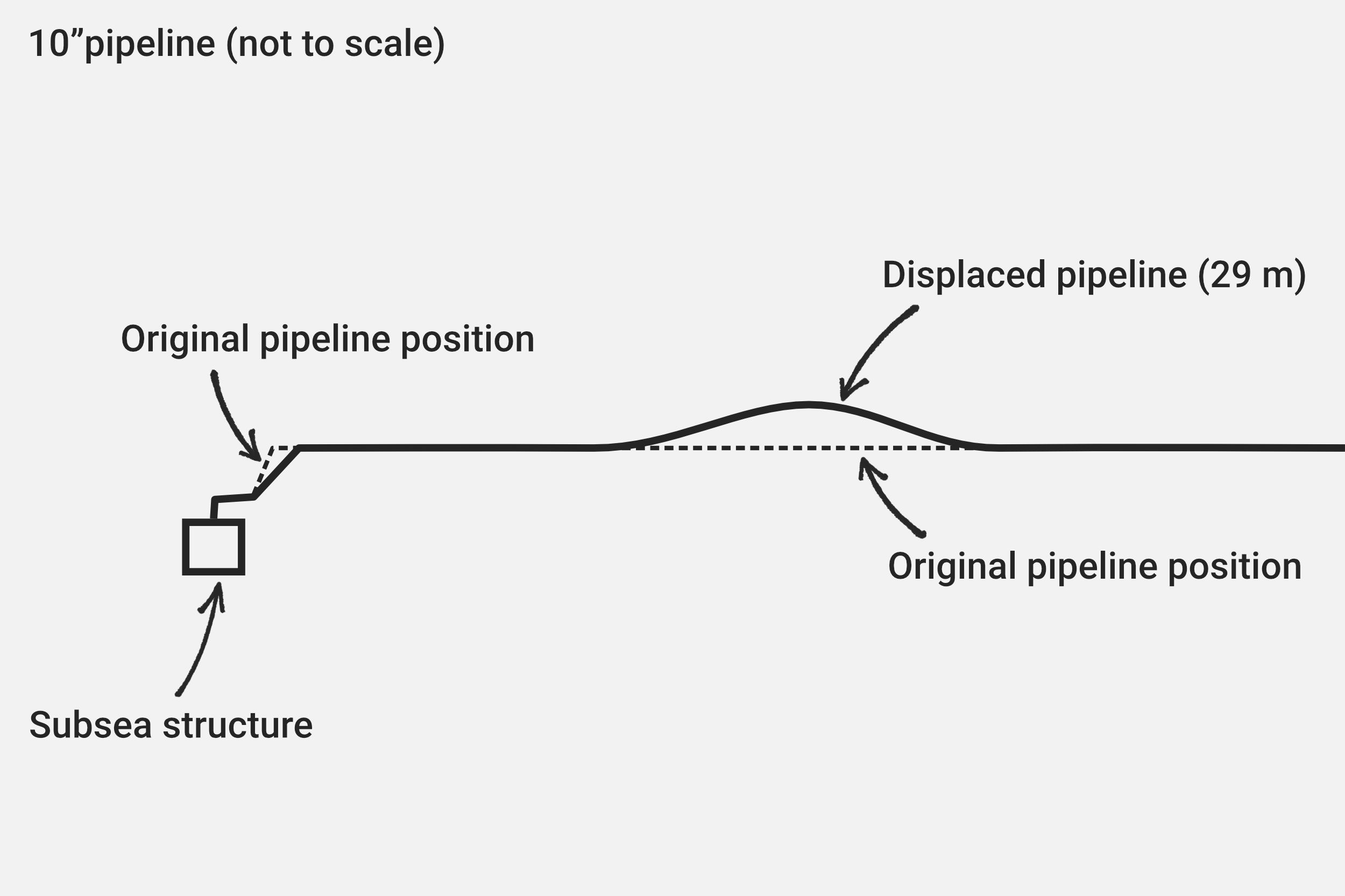
Our client’s customer (a global oil producer) identified evidence of an anchor drag on one of its 8” and 10” subsea pipelines in Thailand, with the 8” pipeline being displaced 16 m and the 10” displaced 29 m from their respective as-laid positions. The 8” pipeline had displaced to such an extent that it crossed an adjacent 6” pipeline at two locations. Each event occurred close to the pipelines’ tie-in locations to subsea manifolds, so spool-pieces had also been displaced.
RJDP completed local buckle analyses of each pipeline to DNVGL-ST-F101 and assessed flange load using Kellogg’s equivalent pressure formula. Our client used outputs from these analyses to undertake an Engineering Critical Assessment (ECA) to assess crack growth through fatigue.
Outputs from this technical assessments would be used to determine if the customer needed to undertake further inspections and remediation works on the pipelines.
Our approach
Data review and initiation
We reviewed all customer provided documentation and data including pipeline surveys, drawings, field layouts, spool-piece drawings, and alignment sheets. Key input data and reference materials were extracted from this documentation and stored in registers for review, approval, and quick access.
A calculation register was built to log all calculations, load cases, and revisions.
Quality control forms were sourced from the client in preparation for calculation and FEA model checks.

Analysis
We coordinated with our client to determine the appropriate simulation strategy, input data, and load cases.
Input decks were used to build the FEA models, improving modelling efficiency and flexibility. These defined each pipeline system’s geometry, operating conditions, element type and node density, operating conditions, seabed friction, and load steps.
Load steps included
Applying gravity and buoyancy to the as-laid pipeline geometry.
Introducing operating pressure and a change in boundary conditions.
Iteratively displacing the pipelines to match their deformed shapes; iterations included changes to seabed friction, direction of anchor drag, and the location of anchor impact.
For the 8” pipeline only, adjusting the model to represent its elevation change where it crossed the adjacent 6” pipeline.
We simplified the modelling approach by not simulating the physical contact between the anchor and pipeline surfaces. This improved modelling and simulation efficiency.
We leveraged overnight batch processing of multiple FEA iterations, reducing chargeable hours to the client.
Mathcad and Excel were deployed for post-analysis data extraction and local buckling and flange load assessments.
All calculations and input decks were thoroughly checked and approved before concluding on the results.
Conclusions and recommendations
The 8” pipeline was found to be within code limits for combined loads according to DNVGL-ST-F101. However, the flanges failed Kellogg’s equivalent pressure formula check, indicating they may have been overloaded during pipeline displacement.
The 8” pipeline being displaced over the adjacent 6” pipeline is not permissible under pipeline codes. It was recommended that these pipelines be separated to prevent corrosion risk.
The 10” pipeline, while showing high stresses and bending moments, was unlikely to undergo plastic deformation at its bends based on the observed and measured displacement curvature.
It was recommended that both pipelines were inspected at the identified areas of high stress from the FEA and at flanges. An ongoing inspection frequency of 1-2 years was also recommended.
Summary
We effectively supported our client with the analysis of two displaced subsea pipelines in Thailand. Using a range of data sources and deploying FEA, we completed numerous model iterations to converge on one which closely represented the surveyed pipelines - using modelling and analysis efficiencies where possible. The outputs of these analyses supported local buckling check to DNVGL-ST-F101 and the evaluation of flange loads. We were able to support our client within the allowable budget to provide suitable conclusions and recommendations to its customer, helping mitigate the risk these pipelines present.
Let diver™ solve your toughest project challenges
At diver™, we partner with you to tackle your most challenging projects, bringing a data-driven, solution-focused approach that empowers your team and drives project success. Start your journey toward a new approach to project execution by contacting us today.